SIGBOTS
"HEY DO YOU WANT TO NOT SLEEP AND BUILD ROBOTS INSTEAD?" "ALWAYS!"
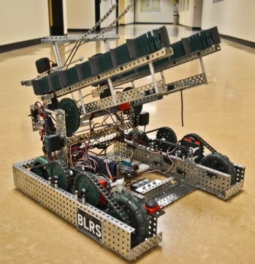
Vex robots are completely re-built each year to compete in the VEX U competition. I help form and grow a club. Other projects ensue.
ACM SIGBOTS
The Association for Computing Machinery's Special Interest Group in Robotics at Purdue
Leader x4
Co-President, Chief Engineer, Mechanics Team Lead, and Founding Member
Lead Engineer
Designed, Iterated, and Built the Mechanics of Robots for World Championships
R&D Projects
Led Research and Development for all Hardware Projects, including those below
The Purdue chapter of ACM SIGBOTS competes each year in the World Championship of the VEX U inter-collegiate robotics challenge. Each year a new challenge is presented, usually some variation of picking up oddly shaped items of a specific color and moving them into goals while preventing the opponent alliance from doing so, and always requiring the complete redesign of both robots per team each year. College-level teams build both robots per alliance (aka team), each inside of a given footprint, and with hardware limitations, with the caveat of allowing custom sensors.
• Grew club from 5 members to near 50 in its first 3 years of existence.
• Split the day-to-day duties of club logistical and financial management, planning and running meetings/work time, etc. with other Co-President
• Event Coordinator and Master of Ceremonies for each club hosted event
• Designed our first shirts and logo

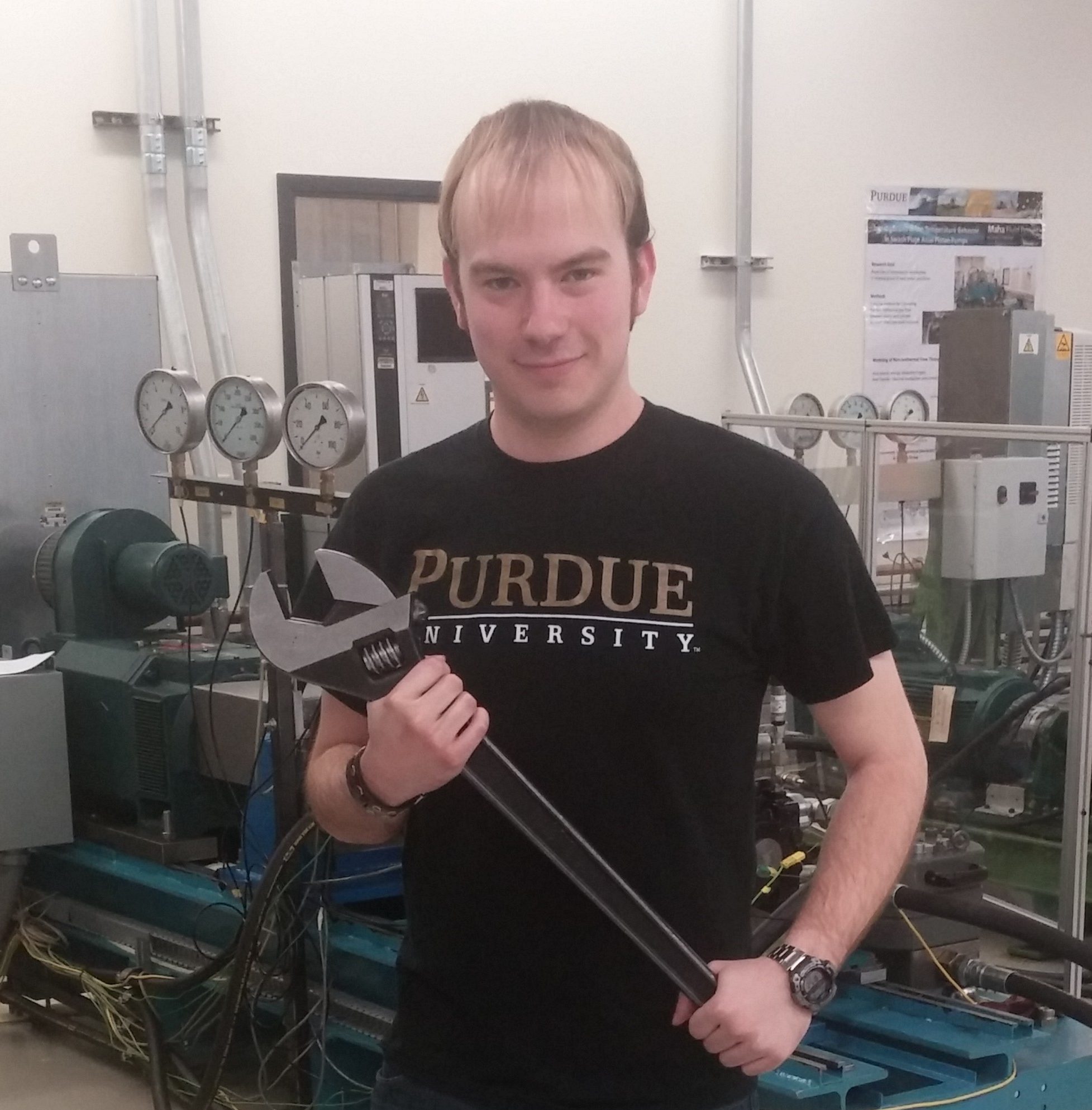
• Oversaw all non-software projects within the club: Annual Construction and R&D. This included not only the annual redesign and construction of robots (see role below) but also our integration between our three “sub-teams” of Software, Electronics, and Mechanics and our special projects (below)
• My most hands-on role
• Coordinated personnel and duties
• Primary for all prototyping, testing, and building
• Acted as a sounding board for feasibility of new design ideas
• Directly oversaw progress by 20-50% of the club membership (with widely varying previous experience, vision, and interest)
• Learned that everyone doesn’t have the same “basic” skills-- I once watched a new member put a bolt through a single piece of metal and then secure it by tightening a locker collar down on the threads. It was then I realized how much I had underestimated the difference in starting experience.
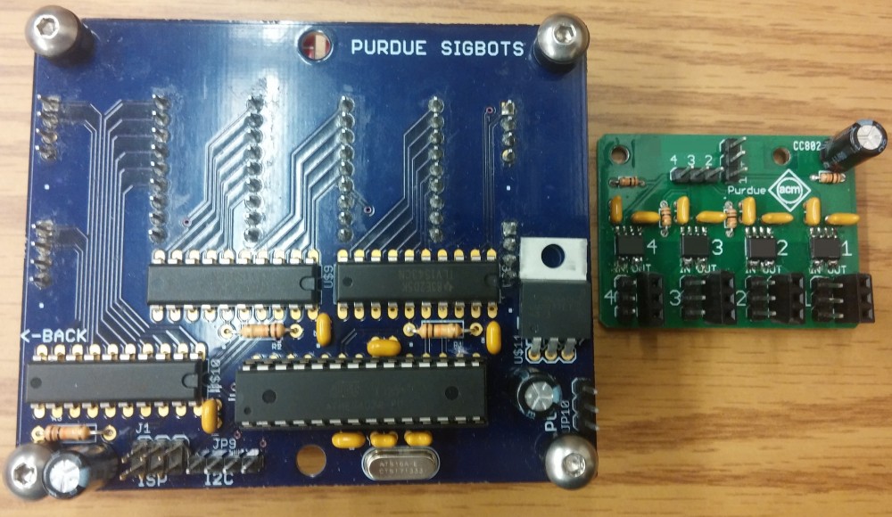
The top of the radius array (L) and Watchdog ver. 1 (R)
Although one of many side projects designed and constructed by Stephen Carlson (another leader in the club and frankly the greatest Electrical/Electronics Engineer I’ve ever met), Project: Watchdog* was my brainchild.
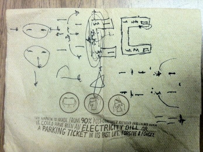
Inspired by a game rule loophole (based on overly specific wording):
After a few years of explaining said loophole to judges, it was finally closed in 2015.
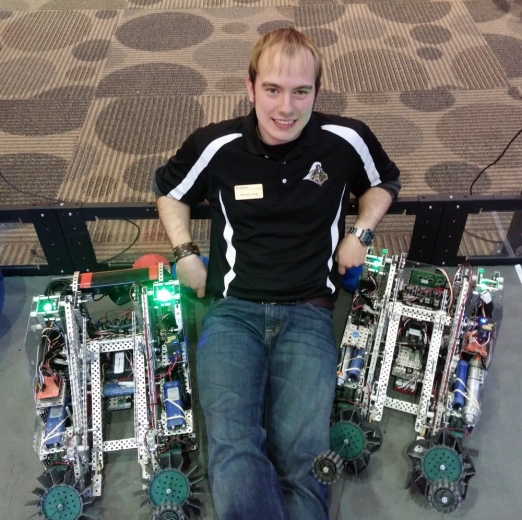
Project: Watchdog was envisioned to function both as a testing device and a sensor during competition. It allows for in-situ testing of motors/drivetrains by looking for cyclical power jumps. It also is part of an AI/driver feedback system (colored LEDs) allowing either controlling entity to know when motors are close to stall (stuck or pushing).
Watchdog LEDS in Action
Other projects from the team include:
- PROS (Purdue Robotic Operating System) — Assembly level optimized non-interpreted OS for the VEX Cortex microcontroller. Free, powerful, and quickly gaining market share over expensive “educational” software
- Powered Programming Adapter* — allows controller to flash robot code while remaining on wall power
- Radius Array* — array of IR line sensors that greatly increase line tracking ability, uses one of my custom cases
- Others including intelligent mapping, 3D target recognition (aka “Hunting”), and other AI work
* Denotes custom PCB circuitry
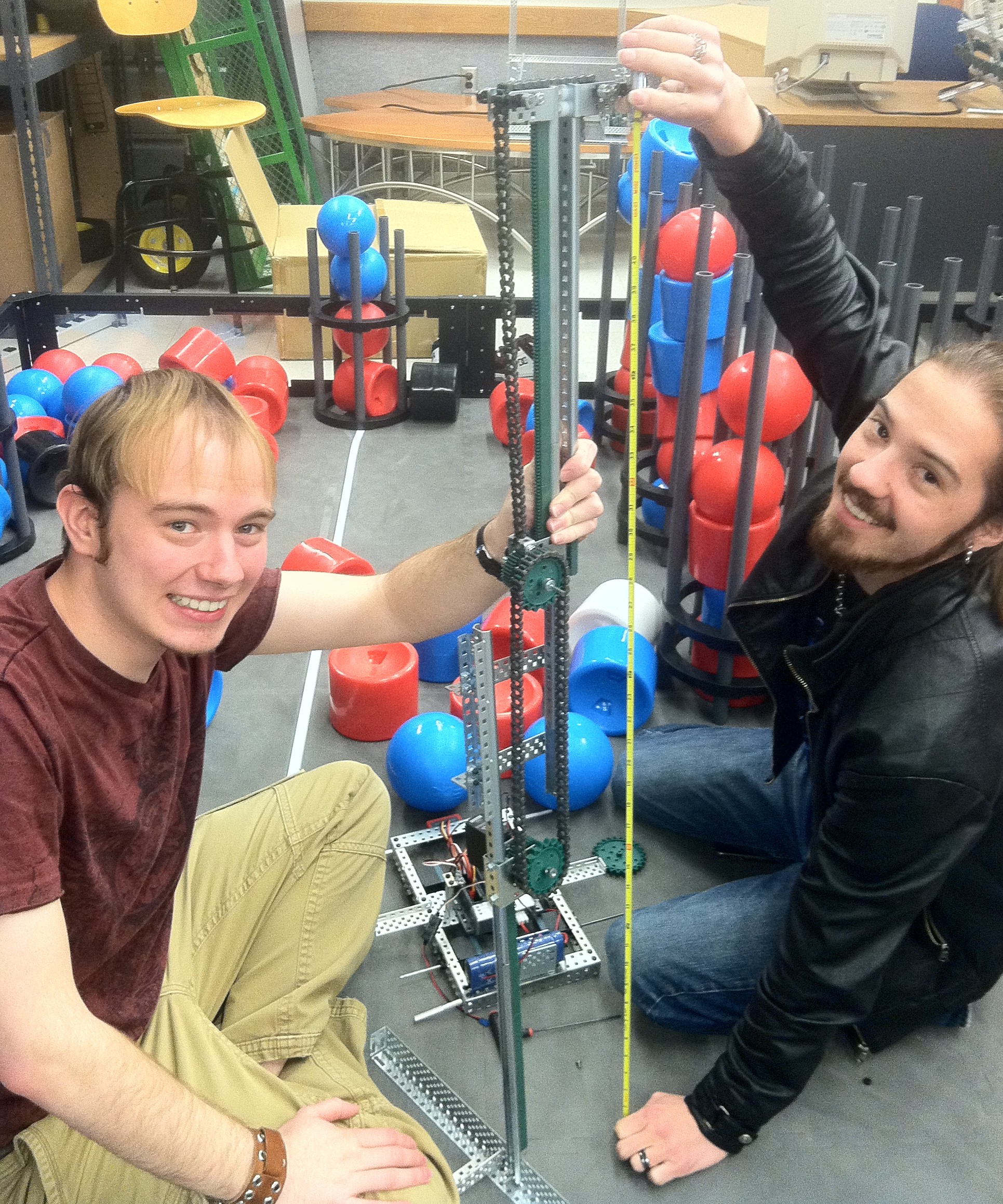
SYRaP [pron. Syrup] Lift — SYnced Rack and Pinion Lift. A mechanism of my design capable of lifting a point vertically from very bottom of mechanism to very top (very little offset from ends). Typically capable of Δs close to 200% of the collapsed height.
Operation: A single pinion is bookended by matching racks. As the pinion is turned, the racks are driven equal amounts in opposite directions. Since the system is mounted at the bottom of the lower rack, this moves the top of the upper rack up. The second half of the assembly is the “multiplier,” consisting of a sliding truck that slides on the back of the upper rack. The lift point is on this truck. As the racks separate a chain attached to both the top of the lower rack and truck is drawn up and over the top of rollers on the upper rack pulling the truck upward. This means the truck travels from mount height (i.e. the ground) when collapsed and the top of the top rack/truck rail when extended (see below).
As the size and importance of the custom circuitry used in our robots increased from one year to another, we eventually became worried that our creations might become damaged or tangled as part of normal use and gameplay. In order to preserve both the hardware and the aesthetics of our robots I designed and printed custom cases for these components in ABS (so we could chemically weld them if needed).
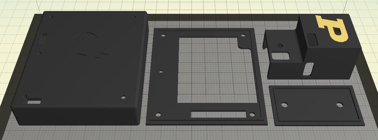
Cases for the Radius Array (L) and a power supply board (R)
Each case was designed to ensure the board’s wires stayed firmly seated and LED indicators were visible, while adding protection and cable management. The bottom plate of the radius array case seen above includes a large oddly-shaped space in order to allow the bottom of the board to see the floor to track the lines of the playing surface. The yellow (actually printed in gold) was printed separately and welded to the larger piece with acetone. Features include fillets on interior edges near connectors and wires and outer edge reinforcement on the inside of all holes. The cases did their jobs well and were well received.
